FreeCAD TechDraw — Technical Drawings
Workbench reference · Updated May 2026 · 7 min read
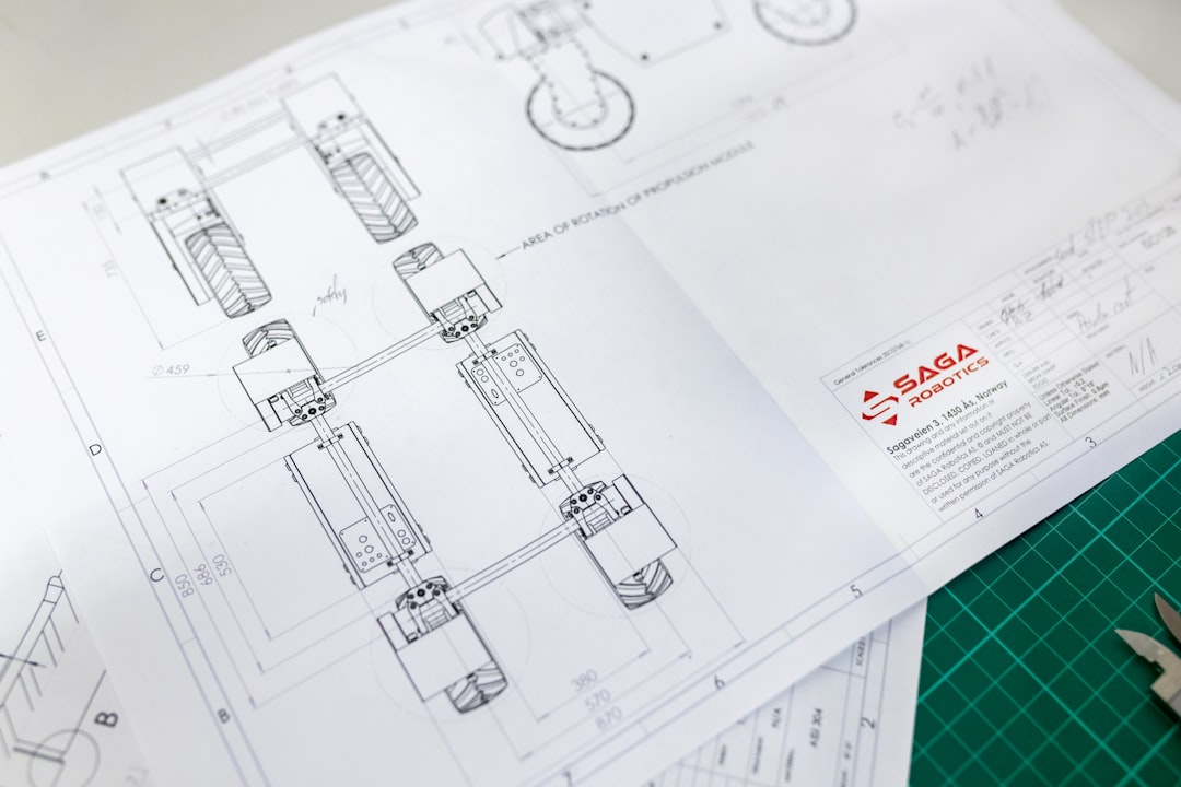
TechDraw is FreeCAD's technical-drawings workbench — generate orthographic projections, sections, isometric views, and dimensioned shop drawings from your 3D models. The output is what you hand to a machinist, contractor, or fabricator to build the part. Export as PDF for printing, SVG for further editing, or DXF for handoff to AutoCAD users.
TechDraw is the modern replacement for FreeCAD's older Drawing workbench (deprecated). If you've used SolidWorks Drawings or Inventor Drawings, TechDraw will feel familiar — it's the same conceptual model: place a 3D model on a 2D sheet, generate views, add dimensions and annotations.
When you need TechDraw
Anyone you hand off design files to who isn't going to open the .FCStd in FreeCAD — machinists, fabricators, contractors, regulators — wants drawings, not 3D models. TechDraw produces those drawings:
- Shop drawings for a CNC machinist with toleranced dimensions.
- Welding shop drawings with weld symbols and sectioning.
- Architectural sheets for permitting and contractor handoff (combined with BIM).
- Patent drawings showing invention details.
- Assembly drawings with bill-of-materials callouts.
The TechDraw workflow — five steps
- Build the 3D model in Part Design (or Assembly, BIM, etc.).
- Insert a Page: TechDraw → Insert page using template. Pick A4, A3, ANSI Letter, etc.
- Add views: select your 3D model, click Insert view. Front, top, side, isometric.
- Annotate: dimensions, leader lines, notes, balloons (for assemblies).
- Export: PDF for print, SVG for vector edit, DXF for AutoCAD users.
Page templates — A4 to ANSI E
FreeCAD ships templates for standard sheet sizes:
- ISO standards: A0, A1, A2, A3, A4 — used in Europe and most of the world.
- ANSI standards: A (Letter), B (Tabloid), C, D, E — used in the US and Canada.
- Templates with title block: pre-drawn frame with company name, drawing number, scale, date fields. Edit by clicking the placeholder text.
Custom templates: SVG files at /data/Mod/TechDraw/Templates/. Edit one in
Inkscape to add your company logo or change the title-block layout. Save as a new template,
use across all your projects.
Views — types and what each is for
- Standard view: orthographic projection from a chosen direction (front, top, right, isometric, custom).
- Projection group: multiple aligned views in one operation — front + top + side, all aligned, all at the same scale.
- Section view: cut the model with a plane, show what's inside. For interior features.
- Detail view: zoomed-in portion of an existing view. For tight tolerance areas.
- Broken view: long parts shown with a "break" so they fit on a smaller page.
- Complex section: multi-step cut along a polyline, not just a plane.
- Spreadsheet view: table from a FreeCAD Spreadsheet — bill of materials, dimension tables.
Dimensions — types
- Distance (linear): straight distance between two points.
- Distance horizontal / vertical: projected on the X or Y axis.
- Angle: between two lines or three points.
- Radius / Diameter: for arcs and circles.
- Length: length of an arc or path.
Tolerances: each dimension can carry a tolerance — symmetric (±0.05), asymmetric (+0.10 / -0.05), or limit dimensions (10.05 / 9.95). The tolerance appears next to the dimension number on the drawing for the machinist to read.
Annotations and symbols
- Notes: free-form text anywhere on the page.
- Leader lines: arrow with a note attached. For callouts.
- Centerlines: auto-generated for round features.
- Balloons: numbered callouts for assembly drawings, linking to a bill of materials.
- Hatching: auto-generated cross-hatch pattern in section views (different patterns for different materials).
- Surface roughness symbols: Ra/Rz callouts for machined faces.
- Geometric tolerance: GD&T frames for flatness, parallelism, position, etc.
- Weld symbols: standardized welding callouts (fillet, butt, plug, slot).
Export formats — what to use when
| Format | Best for | Trade-off |
|---|---|---|
| Print and email | Not editable; recipient can't change anything | |
| SVG | Further editing in Inkscape, web display | Some apps don't render TechDraw SVG layers correctly |
| DXF | Handoff to AutoCAD users | Loses some FreeCAD-specific styling; dimensions become drawing entities |
Updating drawings when the model changes
TechDraw views are live-linked to the 3D model. Change a dimension in Part Design, the TechDraw views regenerate automatically (or with one click — TechDraw → Update view). Dimensions you placed on the drawing keep their leader positions; the values update to match the new geometry.
This is the parametric advantage applied to drawings: revise the model, the entire drawing set updates. Comparable to SolidWorks drawings or Inventor drawings — the model is the single source of truth, the drawings are derived.
Tips for production-quality drawings
- Use a template with your title block. Looks professional, includes drawing number, revision, scale.
- Set scales explicitly. Don't let TechDraw auto-scale — pick 1:1, 1:2, 1:5, 2:1 for clarity.
- Group related views. Use Projection Group instead of placing views individually — keeps them aligned and at consistent scale.
- Section heavy parts. If a part has internal features, a section view is the only way to dimension them properly.
- Hide construction geometry. Centerlines and origin axes shouldn't show on the final drawing.
- Use detail views for tight features. 5x zoom on a fillet that needs ±0.02 tolerance is much clearer than tiny dimensions on the main view.
Try TechDraw — FreeCAD 1.1.3
Professional drawing output. Free for Windows, Mac, Linux.
Download FreeCADRelated guides
Part Design — solids
Build the model that TechDraw documents.
BIM — architecture
Generate floor plans and elevations from architectural models via TechDraw.
vs AutoCAD
TechDraw covers most AutoCAD drawing use cases without the subscription.
All Workbenches
Part Design, Sketcher, FEM, Path, BIM and more.